The short answer
Magnet polarity on miniatures is a pairing problem. The two flat faces that meet inside a joint must present opposite poles, because unlike poles attract, and you cannot tell which pole is which by looking. So glue one side first, keep its exposed mating face as your reference, and test every interchangeable part against that reference before adhesive goes near the joint.
A compass can identify a pole when it is used correctly, but for relative matching you do not need one. You need a reference you trust and a check you repeat. Size and adhesive are separate decisions, covered further down.
Which magnets this method suits
The face-to-face check assumes axially magnetized disc magnets: the common type sold for interchangeable arms and weapons, with poles on the two flat circular faces and magnetization through the thickness. It also assumes those flat faces are the ones that will meet in the finished joint.
It is not a universal test for every magnet sold to hobbyists. Radially magnetized rings, multipole magnets, block magnets used edge-on, and magnets set into a steel cup or housing can present more than one pole on a surface, or hide the pole pattern behind a housing. If the maker does not state the magnetization direction, treat the test as unconfirmed for that part and check with the supplier rather than reading one result as proof.
Two faces meet, and they have to be different
Every magnetized joint has two halves: the face exposed in the body socket and the face exposed on the arm or weapon that plugs into it. They are different faces on different magnets, and in use they meet. For the part to hold they must attract, so one has to present the opposite pole of the other.
Install a body magnet with one face out, then install the arm magnet with the same face out, and the faces that meet present the same pole: they push apart. Both halves can look consistent and still be wrong as a pair. Depth is a separate question — a magnet sitting too deep changes whether the faces get close enough to hold, not which face is which.
Why "north out" is not the rule
The usual advice is to glue every magnet north side out. Even when poles can be read reliably, that cannot be right for both halves of a pair: if the socket face is north, the arm face has to be south. Same face on both sides means repulsion, not a hold.
A dot on an arbitrary face does not identify geographic or magnetic north, and it does not need to. The dot records a role, such as "this face mates with that socket", which is all the assembly needs.
Glue one side first, then derive the rest
Work in this order, and keep loose magnets on a tray with a lip so they cannot roll away.
- Choose what the first magnet has to match. In a new, independent interface group, either orientation can define the reference, because nothing is established yet. If you are matching an existing army or part set, test a candidate against that established reference first, so the first orientation is copied from evidence rather than picked arbitrarily.
- Glue the reference magnet and let the adhesive reach the maker's specified cure. A magnet still moving on soft adhesive can be pulled out or turned by a test magnet. Wait for the stated cure time before using it as a test reference. If work has to continue sooner, use a separate loose reference magnet that is labelled with the face it presents, and keep the installed magnet out of the test.
- Mark the mating flat face, not just the rim. A rim mark records position but does not by itself say which of the two flat faces is meant. Put a small mark on the mating flat face where it will not sit under the adhesive, or keep the magnet in a labelled orientation holder or cup that always presents the same face. Dry-fit the part and recheck the mark against the intended faces before gluing. Keep the bonding surfaces suitable for the adhesive as labelled; a mark across a glue face can weaken the bond.
- Check each arm against the same body reference. Bring the loose magnet's intended mating face towards the fixed reference face, parallel and on the same axis, and hold it so it cannot flip or spin. If the set already exists, that established reference is the one the new part has to match. Arm-to-arm attraction is not a substitute for testing against the body reference.
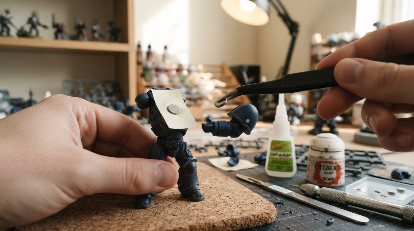
Repeat the same two checks for every other arm for that socket: mark the mating flat face, then test the candidate against the same body reference — never against the arm you finished last.
With several body sockets, seat each new body magnet dry and test it against a finished arm before gluing: the face that pulls towards the arm's mating face is the one to leave exposed. Do that only after the finished arm's adhesive has cured, or against a labelled loose reference for that arm. Every socket then shares one outward face, so one set of arms fits all of them. If a socket you have already glued pushes the arm away, it is the odd one out: label it and keep its arms in a separate group.
The Army Painter's own how-to on its miniature magnets ends with the same requirement in one line: copy the process on the other side, "but make sure that your magnets has the correct facing to connect both magnets" (The Army Painter). The page states the requirement without explaining how to find that facing, which is what the barrier test supplies. Its 1 mm-deep hole example belongs to that product's 3x1 mm and 5x1 mm magnets, so treat it as a product-specific starting point, not a depth rule.
Test the pair through a barrier
The separator does two jobs: it stops the magnets slapping together and chipping a painted edge, and it gives you a controllable gap instead of a sudden snap. It does not turn the test into a measurement.
Align the intended faces before you judge. They should be parallel and on the same axis. A sideways kick or slide is not proof that equal poles are facing each other: lateral misalignment and free rotation can produce that feel even when the poles would attract once aligned. Hold both parts so they cannot flip, check that the flat faces you mean are actually the ones facing, and retest before drawing a conclusion. No single movement is a certain polarity verdict.
Use a separator you know is non-ferrous. Paper, card and tape are suitable; a steel rule, metal feeler gauge or steel tray is attracted to either pole and can mask the intended pair or create a pull that seems to confirm the wrong arrangement. If you cannot identify the separator material, change it rather than interpreting the feel.
"No pull and no push" does not identify a ferrous barrier. It is an inconclusive result: the magnets may be too far apart, the faces may be misaligned, the separator may be interfering, or the magnet may be weak. Reset the distance and alignment, switch to a known non-ferrous separator, and retest. Do not diagnose the barrier from feel alone. A weak pull is not a strength guarantee either, because the gap is part of what you are feeling.
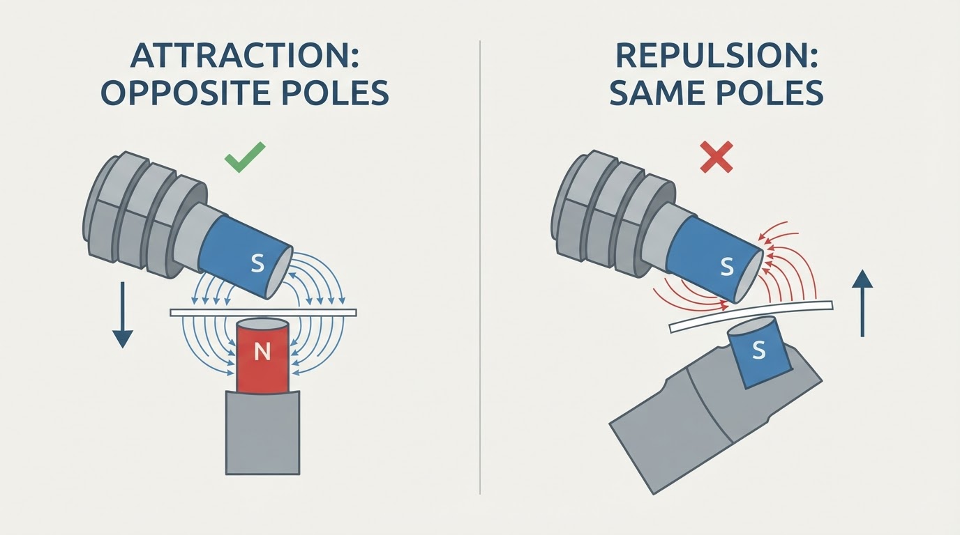
A paper separator reduces direct contact and contamination; it does not guarantee that magnets cannot snap together, pinch skin or chip an edge. Keep fingers clear, hold both parts securely, and work over a tray.
Check every spare, not just the last one
A batch can drift when each new arm is compared with the one you finished most recently. One wrong arm becomes the reference for the next, so the error carries forward: arm two is tested against a wrong arm one, arm three against a wrong arm two, and the whole group now agrees with the mistake.
Compare each spare with the fixed reference instead: the cured socket magnet, or the labelled loose reference kept for that group. A wrong part then shows up while it is still loose.
Then work one joint at a time: one loose magnet within reach, one arm on the bench, finished parts away from the loose stock. That removes the pile of identical parts where mix-ups start.
Size and adhesive are separate decisions
Polarity decides which face goes where. It does not decide which magnet size fits a base, or which adhesive holds a magnet in its socket. A joint can have correct polarity and still fail because the magnet is too small, sits too deep, or was bonded with a glue that does not suit the materials.
For base sizing, the guide to what size magnets for Warhammer bases treats diameter, depth and base clearance as their own decisions. For bonding, plastic glue vs super glue for miniatures sets out which adhesives suit plastic joints compared with magnets and resin. Settle those choices separately: changing the magnet size or glue does not correct a reversed pair, and reorienting a correct pair does not fix a weak bond.
If a magnet is already glued in wrong
Stop the batch at that joint. Do not keep gluing arms to a pattern you now know is wrong. If the adhesive has not set, follow its instructions for repositioning before it cures. If it has cured, treat force as a last resort: prying, drilling or heating a set magnet can damage the model, the magnet or the socket, and none of those is a universal repair across kits.
A magnet that is wrong for one joint can still be right elsewhere. If the problem is a body socket, make that socket its own reference and derive its arms from it, so it becomes a dedicated interface instead of a mixed-up one. If the problem is an arm, keep it with the body it matches. Label the part either way.
Decision table: what the test can and cannot tell you
What you observe with the intended faces aligned | What it supports | What to do |
|---|---|---|
Steady pull as the faces come together | The presenting poles are likely opposite | Dry-fit, mark the mating flat face, bond the joint, then test the next spare |
Push away while the faces stay aligned | The presenting poles are likely the same | Stop, confirm which flat faces are actually facing, flip the candidate, mark its new mating face, retest against the same reference |
Sideways kick, slide or rotation | Inconclusive: lateral misalignment or free rotation is confusing the feel | Reset to coaxial alignment, secure both parts, retest before classifying |
No clear pull or push | Inconclusive: gap, misalignment, weak magnet or an unsuitable separator | Switch to a known non-ferrous separator, reduce the gap, realign, retest; do not infer a barrier type from feel |
Weak pull that changes with separator thickness | Distance is changing the force | Confirm polarity separately, then judge fit and hold on the assembled parts |
The table checks polarity only as far as a bench test can support it. Once a pair attracts, the depth and size questions still have to be answered on the actual parts.
Steel plate: a joint without a polarity pair
A ferrous steel plate is attracted to either pole of a magnet. Put steel on one side and a magnet on the other, and the joint no longer needs a complementary polarity, because there is only one magnet to orient.
That suits an interface that keeps going wrong, or one where the halves will not stay in step. A magnet sticking to a plate does not tell you which steel you have, since some stainless alloys are weakly or not attracted; test the actual plate before relying on it. The plate also changes the depth of the joint, and whether the hold suits a heavy weapon is a separate question from whether the faces attract.
Keep the loose magnets contained
The US Consumer Product Safety Commission warns that when two or more high-powered magnets are swallowed they attract each other internally and can cause severe internal injury, with such incidents leading to surgery (CPSC). If you suspect magnets have been swallowed, the agency's advice is to seek immediate medical attention.
So keep loose magnets in a closed container, count them back in when a session ends, and keep them away from children and pets. Never hold one in your mouth while both hands are busy.
FAQ
Should every magnet go in the same way?
No. What has to be consistent is the pair, not the whole model. Glue one side first, then derive every mating face from that reference. If all your body sockets test the same way, one reference serves them; if one does not, keep its arms separate.
Do I need a compass or a pole-marking tool?
Not for relative matching. A compass can identify a magnet's poles when used correctly, and a dedicated pole tester does the same job. The reason to skip either here is that the assembly only needs to know which face attracts a known face, and one reference plus a separator answers that directly. A compass is not incapable because it senses the Earth's field; it is simply unnecessary for this decision.
What if I cannot tell which flat face is the mating face?
Use something that tracks the face for you: a labelled orientation holder, a cup that always presents one face up, or a mark on the mating flat face placed away from the glue area. A rim mark on its own does not settle which flat face is meant.
What if two magnets attract but the part still will not hold?
Then the problem is fit, not polarity: a gap from a deep socket, too little magnet face in contact, or a heavy part that needs more hold than the joint gives. Solve that with depth, seating and magnet choice rather than by re-orienting magnets that are already correct.